
Instructions for Installation of the Dual-Mode Component Cooler™ (Click here to check or download the PDF File)
Product Description
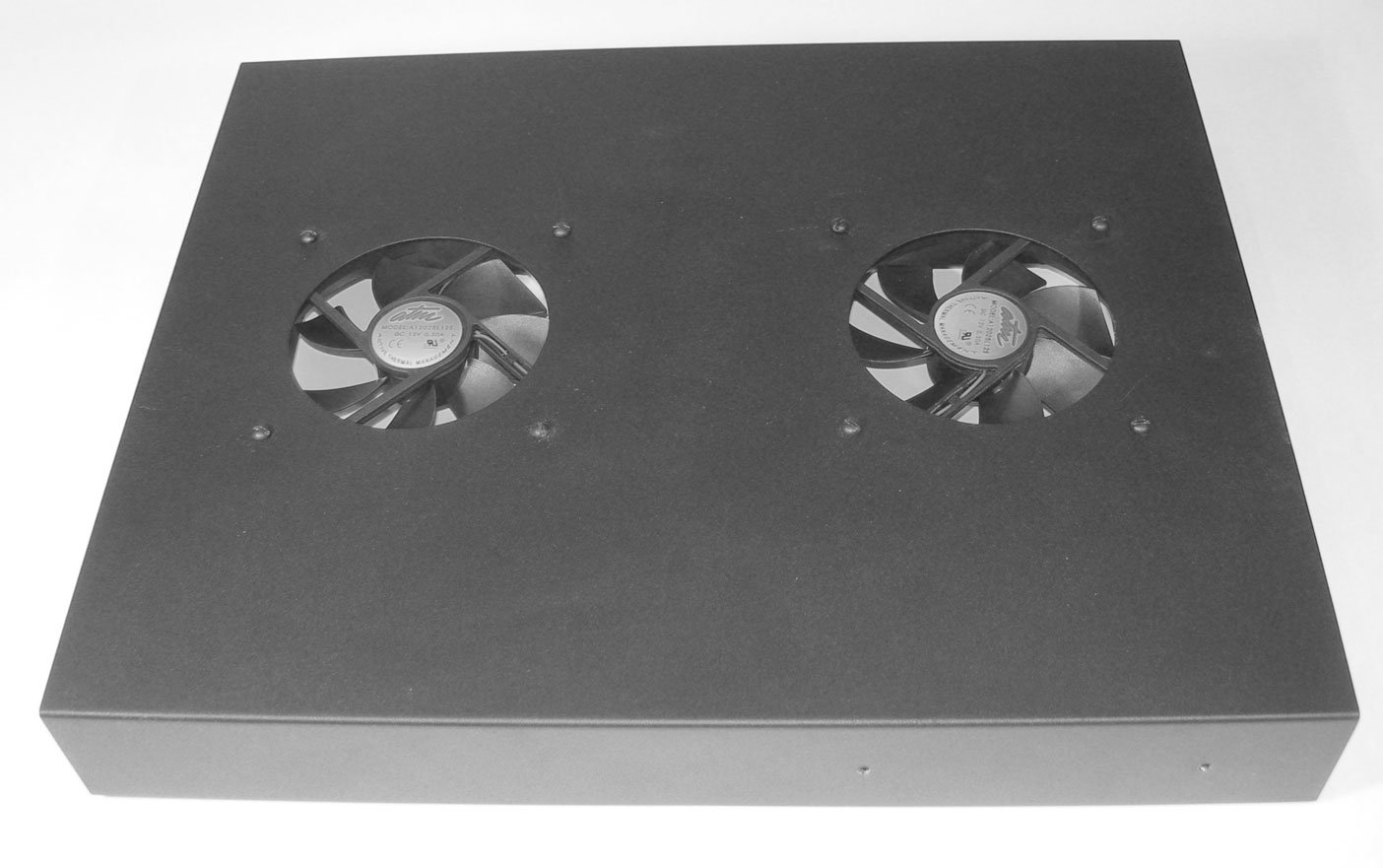
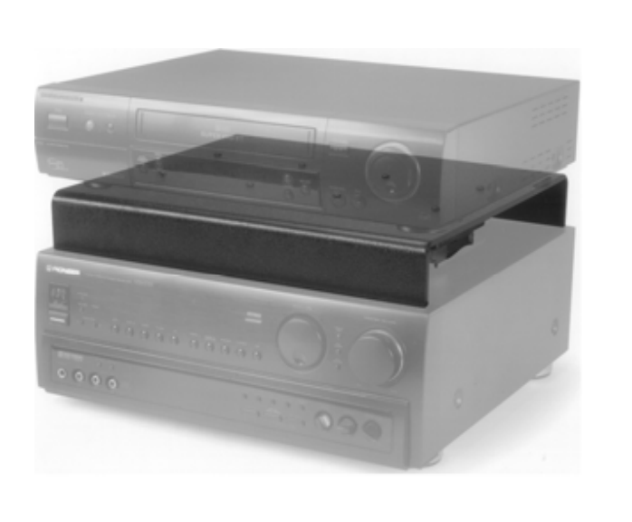
The Dual-Mode Component Cooler is shipped in Shelf configuration. It can be placed on top of a hot component which has ventilation openings in its top cover and will cool it while providing a shelf to support a second component. The second component is shielded from the heat generated by the lower component, allowing more equipment to be placed on a shelf or within a bookcase. Simply place the cooler on the lower (hot) component, then place the preamp, CD player, or other component on top of the Dual-Mode Component Cooler.
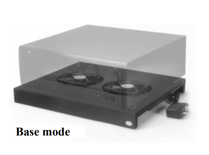
When changed to Base configuration, it can be placed beneath a satellite receiver, DVR/PVR, amplifier, receiver, or any other heat-producing device which has ventilation openings on the bottom surface. Its quiet fans are powerful enough to force a gentle stream of air up through the receiver and out the top or side openings, providing a substantial cooling effect.
In this mode of operation, it is helpful to place foam air dams on the top side of the Dual-Mode Component Cooler to force the air stream to go up into the receiver and not escape through the space between the receiver and the cooler. A length of adhesive-backed foam weather stripping is supplied with each Dual-Mode Component Cooler. When installed, the foam should not allow air to escape under the receiver.
NOTE: The Dual-Mode Component Cooler was designed to cool components in an open, or partially open environment, such as on a shelf, in a bookcase, or in a cabinet with no doors and/or an open back. It cannot cool components in sealed enclosures, as it would circulate the same hot air within the enclosure, providing little cooling. Active Thermal Management offers a complete line of cooling equipment designed to cool entire enclosures, from the smallest to the largest, at www.activethermal.com.
In either configuration, fasten the thermal switch to the part of the component being cooled which normally reaches the highest temperature, using the small magnet supplied. For a surface to which magnets don’t adhere, a small weight or appropriate adhesive tape may be used to ensure good contact between the component and the switch. Note that when in Shelf mode, the thermal switch should be fastened to the component below the Dual-Mode Component Cooler.
Operation
Connect the Dual-Mode Component Cooler’s power supply to an AC power outlet that is always live (i.e., not switched). The fans will turn at a slow speed regardless of temperature, removing the heat generated by many types of equipment when in stand-by mode.
Should the thermal switch sense a temperature rise to approximately 90°F, the fans’ speed will automatically increase. Fan noise is low in both stand-by and full-speed operation.
It is possible that the stand-by speed will be sufficient to cool your component, and that the thermal switch will not activate.
To Change from “Shelf” to “Base” Mode of Operation
Using a Philips screwdriver, unscrew and remove the four long screws, spacers, and nuts holding one of the fans and the plate covering the hole in the top surface of the Dual-Mode Component Cooler. Set the cover plate and spacers aside for possible future use.
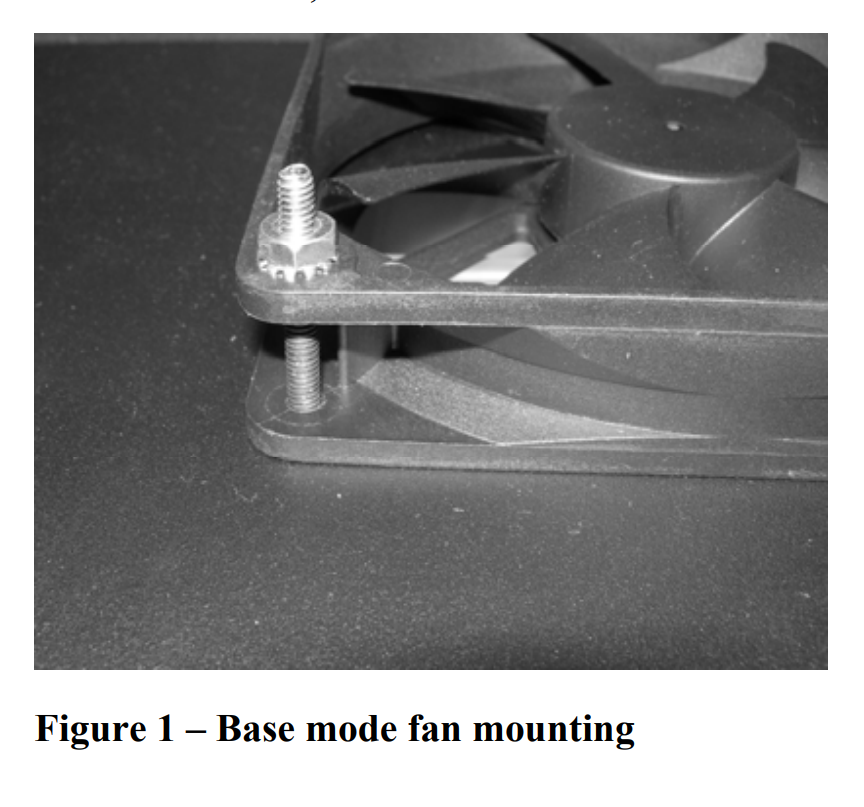
Turn the fan over so that the ATM logo, which faces DOWN in Shelf mode, now faces UP, and insert the four long screws, one at a time, down through the top surface and both holes in one corner of the fan. Leave all screws somewhat loose until all are installed, then tighten all four moderately; do not over tighten. Repeat for the second fan.
When finished, each fan will be attached as in Figure 1, and the ATM logo in the center of the fan will be visible through the top surface of the Dual-Mode Component Cooler.
To Change from “Base” to “Shelf” Mode of Operation
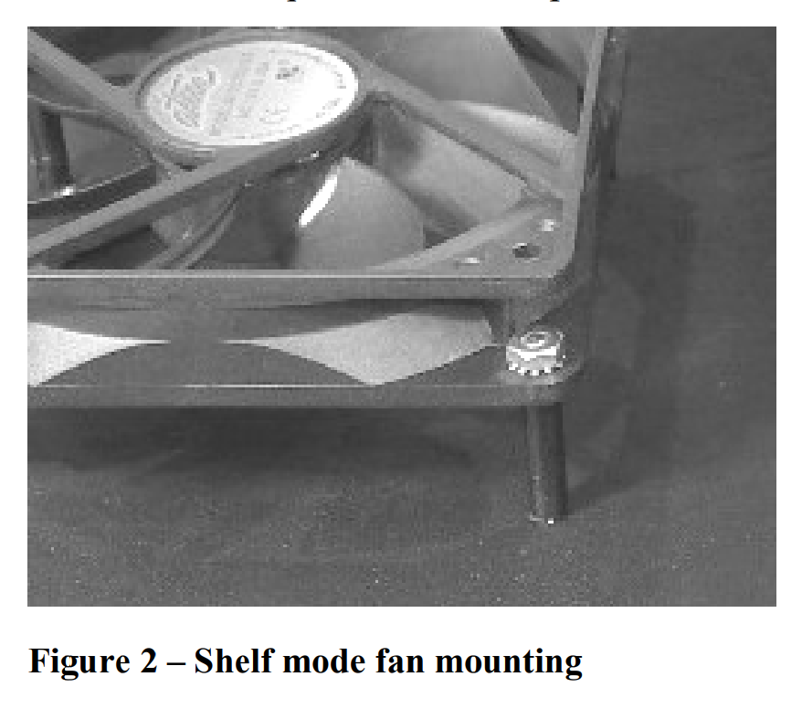
Remove the four screws and nuts holding one fan to the top surface and turn the fan over so that the ATM logo faces DOWN. Put the screws, one at a time, through the cover plate, top surface, spacer, and fan flange as in Figure 2. Leave all screws somewhat loose until all are installed, then tighten all four moderately; do not over tighten. Repeat for the second fan.
When finished, each fan will be attached as in Figure 2, and the cover plates will be in place.
Figure 1 – Base mode fan mounting
Figure 2 – Shelf mode fan mounting
Warranty
Active Thermal Management (ATM) warrants its products against defects in materials and workmanship for one year from the date of purchase. We will repair or replace, at our option, any ATM product with a defect in materials or workmanship.
The product must be properly packaged and returned prepaid with an ATM return authorization number clearly written on the outside of the shipping carton and with a copy of the bill of sale or ATM invoice to verify the original purchase date.
Our warranty does NOT apply to:
- Shipping damage, either concealed or visible. Claims must be filed with the carrier.
- Damage caused by improper installation or improper electrical voltage.
- Any product which has been modified, unless authorized by ATM.
- Damage caused by corrosion, abrasion, immersion, or severe temperatures.
- Products which have been subject to abuse, misuse, abnormal usage, or accident.
These warranties give you specific legal rights, and are subject to any applicable consumer protection legislation. You may also have additional rights which vary from state to state.
No other warranties, expressed, implied, or written, shall apply to this product. ATM will not be responsible for any consequential or incidental damages, loss of property, revenues, or profit, cost of removal, installation, or reinstallation, personal injury, or for any breach of warranty, regardless of how caused.
Contact Information
25570 Rye Canyon Rd. Suite D
Valencia, CA 91355
Phone: 661-294-7999 (voice)
Fax: 661-294-1115
Email: techinfo@activethermal.com
Website: www.activethermal.com